
Audiomatica Open Source Turntable – codename “Medusa”
Document version 06-08-2024 – This page is a work in progress
This page provides detailed instructions and resources to assist individuals in building and replicating the Audiomatica Open Source Turntable “Medusa”. The Project is provided “as-is” and without warranty of any kind, either expressed or implied. While we make efforts to ensure accuracy and provide thorough documentation, we do not guarantee the functionality, safety, or fitness for a particular purpose. We do not assume any liability for any damage, injury, or loss that may occur as a result of building or using the hardware based on the instructions provided. The Project may involve the use of tools, materials, and processes that can pose risks. Users should exercise caution and adhere to proper safety procedures. We are not responsible for any accidents, injuries, or damage that may occur during the construction or use of the turntable. Users are allowed and encouraged to modify and adapt the turntable for their specific needs. However, any such modifications are at the user’s own risk, and we do not take responsibility for the performance, safety, or suitability of modified versions of the hardware.
This work is licensed under a Creative Commons Attribution-ShareAlike 4.0 International License.

The Audiomatica Open Source Turntable is not sold as a kit or commercial product.
Preface
The idea of an inexpensive, compact yet expandable platform for the polar measurement of electroacoustic devices has been in our minds for a long time. The aim of this project is not to replace commercially available products such as the industry-standard Outline ET250-3D turntable which we do recommend for the polar measurement of loudspeaker boxes. Nevertheless, we always found a market niche void in the polar measurement applications of small and light electro-acoustical devices.
Development of such turntable devices in the past required significant investment. Specific mechanical and motor control design skills were needed, leading to both costly and time-consuming processes. Recent developments in mechatronics and 3D printing allow to design and build a cost-effective solution. Our aim is to create a device that can be easily built with off-the-shelf parts, and at the same time can be tailored to specific customer’s needs using minimal modifications. This can be achieved using a ball-bearing swivel plate driven by a stepper motor controlled by an Arduino microcontroller running Grbl firmware.
This project has been presented at the 151st AES On-Line Convention:
An Open Source Turntable for Electro-Acoustical Devices Characterization
(E-brief, 151st AES Convention, October 2021, by Daniele Ponteggia – 1.66MB Pdf)
Design choices
In our build, we decided to use a small yet inexpensive swivel bearing plate that can be easily found in online shops. Everything in our design turns around, literally, to this choice. These plates can be found online using the keywords “Lazy Susan Hardware” (https://en.wikipedia.org/wiki/Lazy_Susan) and are commonly used for kitchen turntables and rotating stools. Among all possibilities we chose a small and compact “3-inch” model, which can withstand a weight up to 60 kg.:
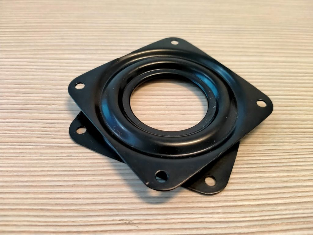
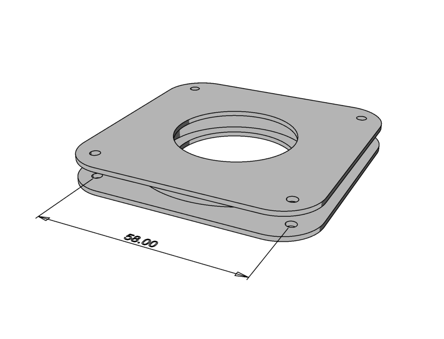
The most important dimension to check in the sourced part is the distance between holes, which has to be 58 mm to fit the supporting structure we designed:
As a motor, we chose a NEMA-17 stepper motor (https://reprap.org/wiki/NEMA_17_Stepper_motor), in our build we used a Wantai 42BYGHW811 which has a step angle of 1.8 degrees, a rated current of 2.5 A, and a holding torque of 47 N·cm. The motor has a 5 mm shaft. Any NEMA-17 stepper motor with similar characteristics should fit the design, the motor we used has a 47 mm body height, the design can accommodate up to 60 mm motor height.
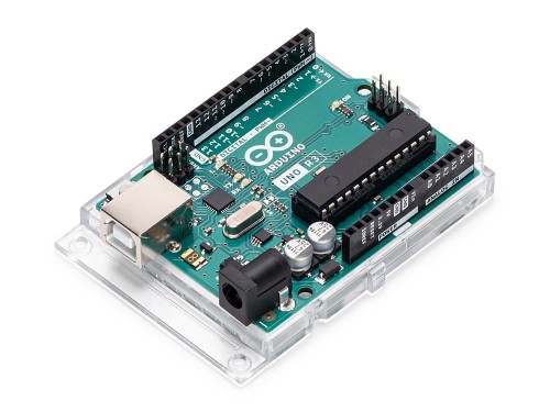
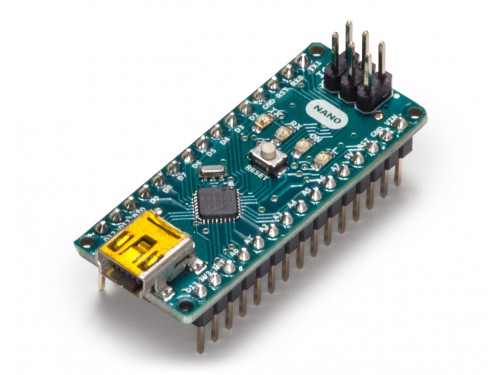
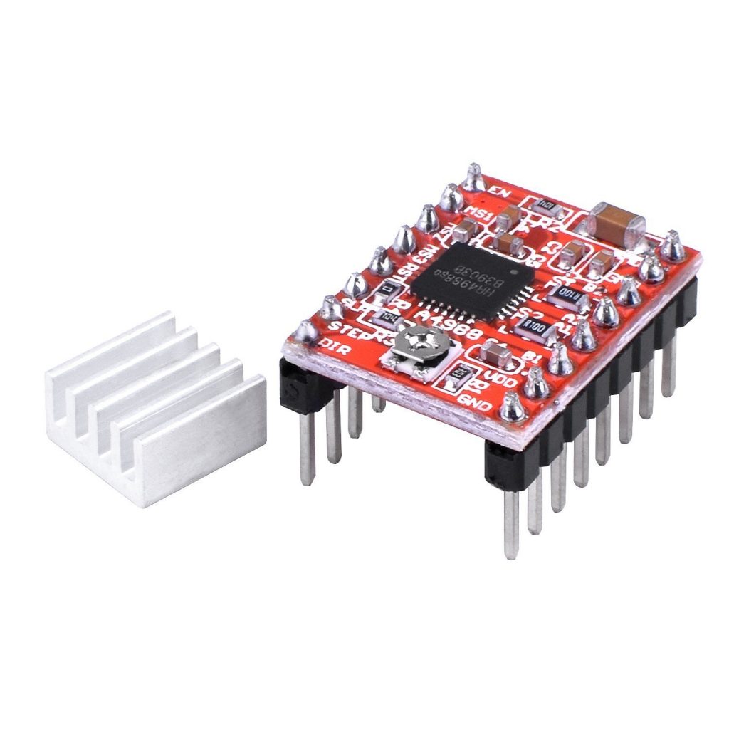
The motor is controlled using a A4988 Stepper Motor Driver connected to an Arduino Uno or Nano.
Boards with the A4988 motor driver are widely available, usually at very low prices.
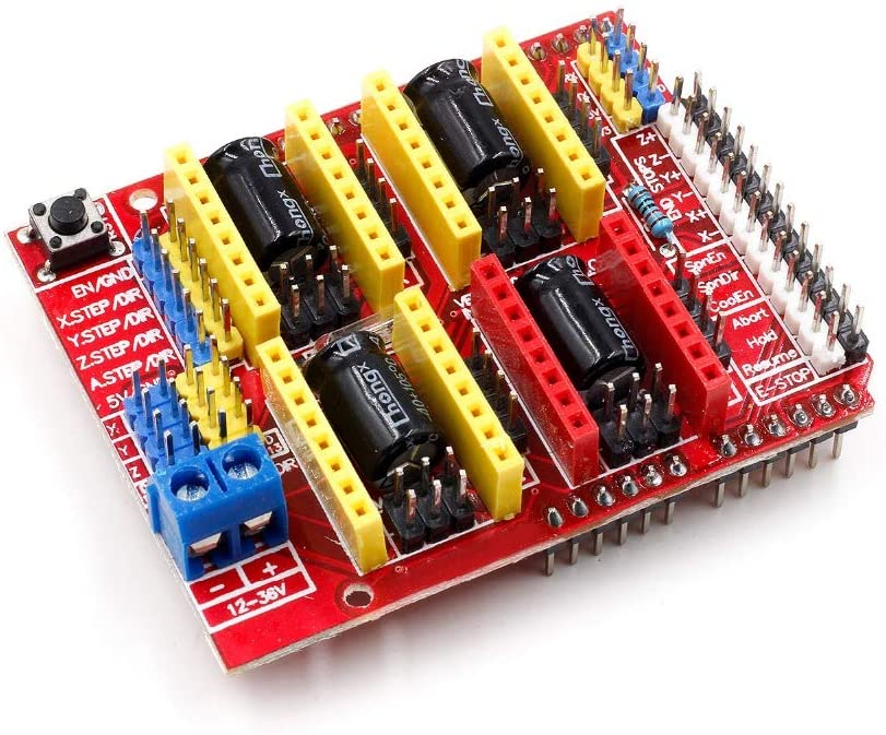
The driver can be connected using few components to the Arduino board, but we wanted to reduce the burden of soldering to a minimum, thus we found two possible solutions with Arduino shields. Using Arduino Uno a possible solution is found on the market as “Arduino CNC shield V3”, this is a shield that can host up to 4 A4988 motor drivers:
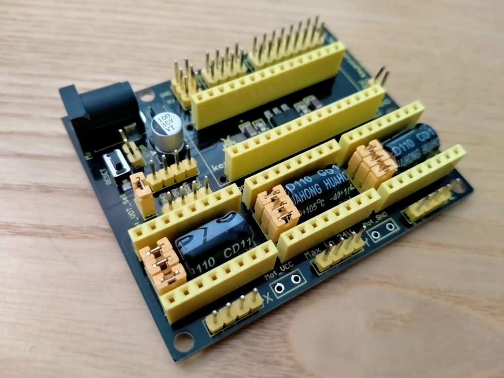
We liked most the compactness and sleek elegance of Arduino Nano and we were able to find a motor shield for it. This can be found as “Arduino CNC shield V4”:
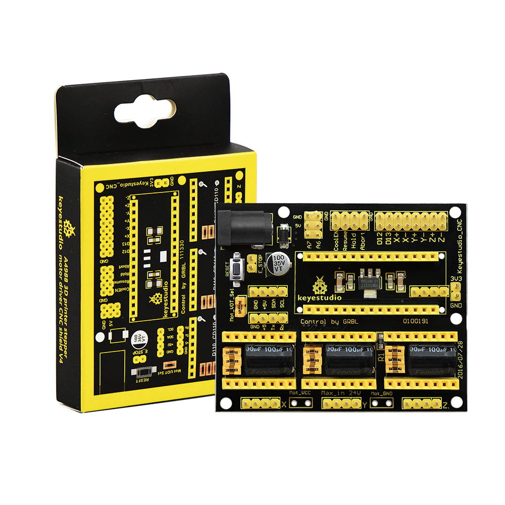
To reduce the time-to-market and reuse all possible components available we decided to not write a custom firmware for the Arduino board and instead use the widely adopted Grbl firmware. This allows sending commands to the turntable using standard CNC G-code and Grbl specific features. Both Arduino CNC shields shown here are compatible with Grbl.
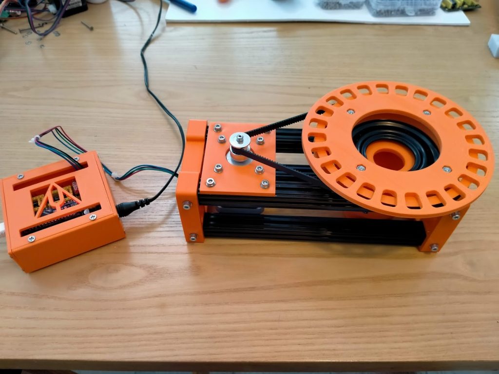
Audiomatica Open Source Turntable v1.0
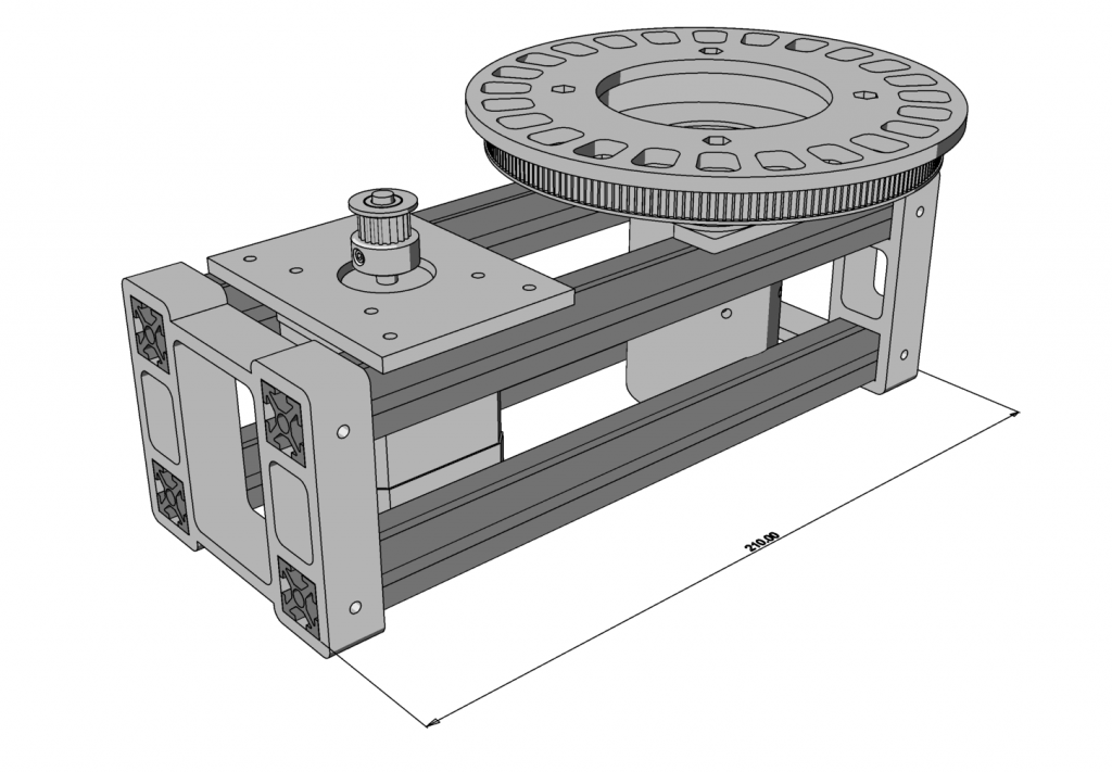
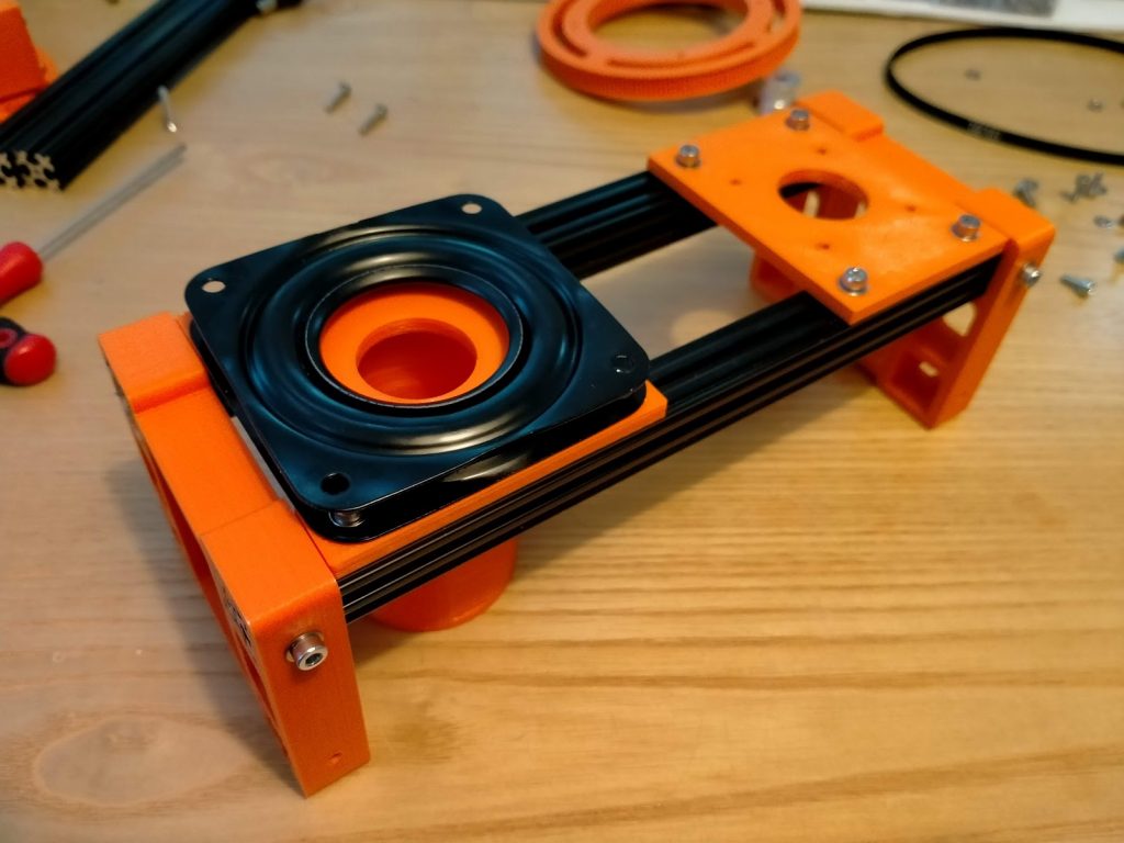
Following the above choices, we designed a structure to hold together the swivel plate and the motor, providing a belt mechanism to drive the table rotation.
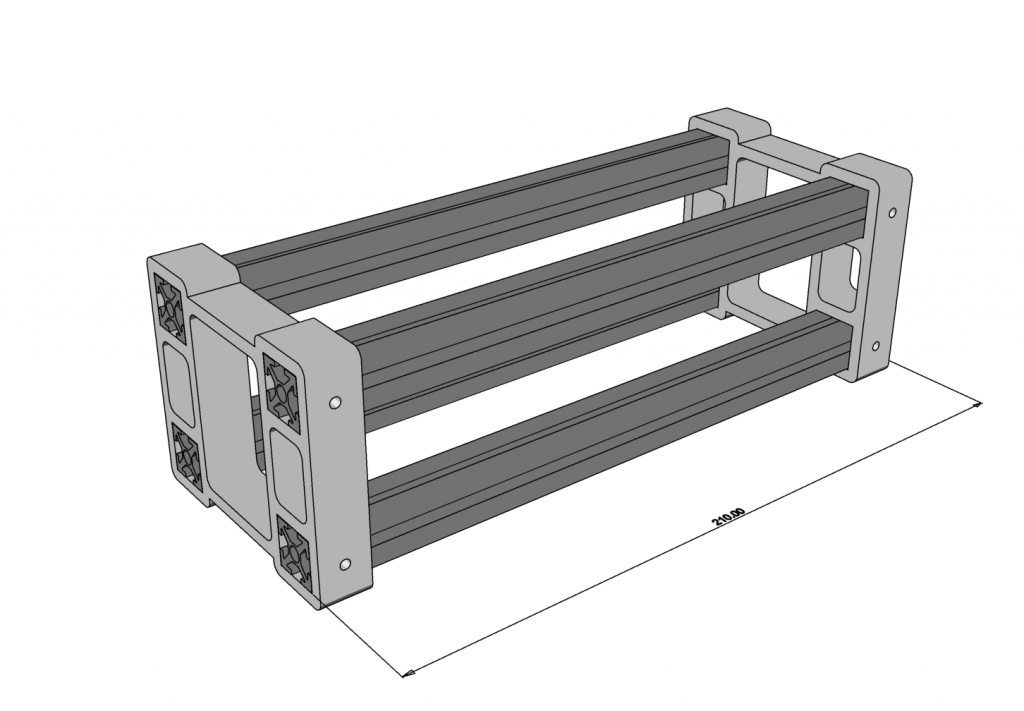
The main structure is composed of four pieces of 210 mm OpenBeam aluminum beams with 15 x 15 mm section connected using two 3D printed parts:
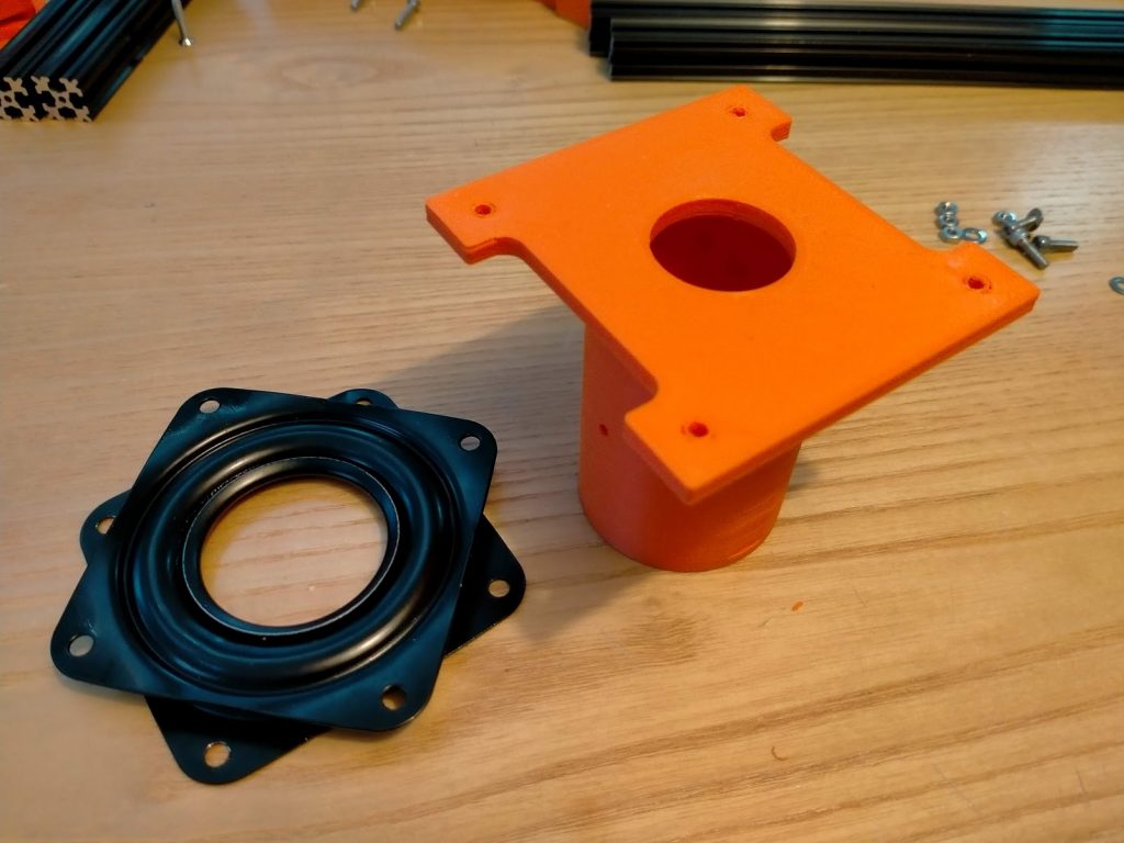
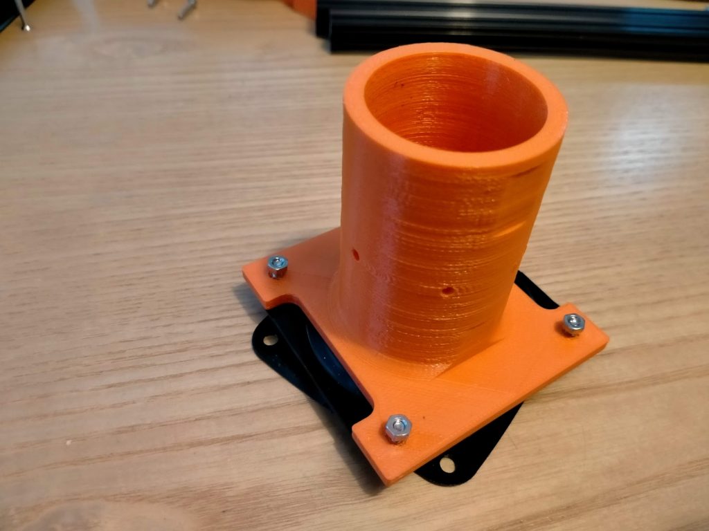
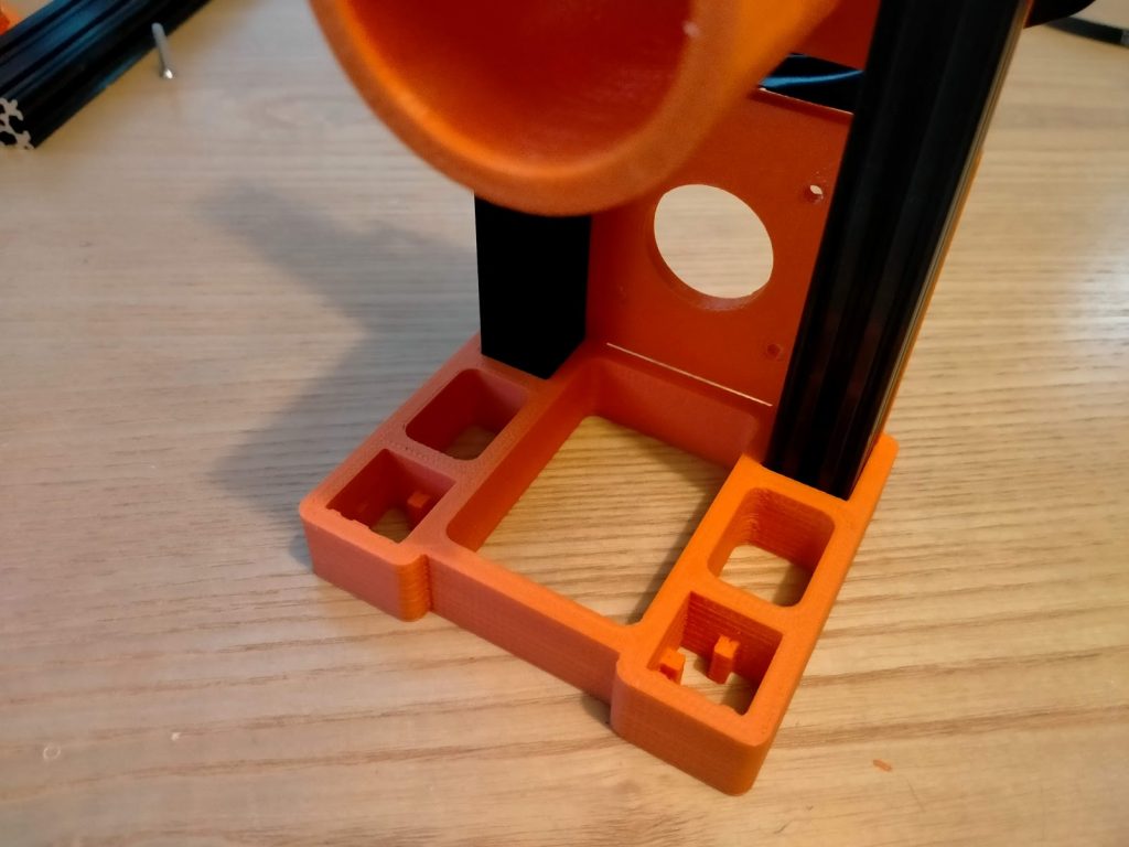
Since we want the turntable to be used on a bench and also mounted on a loudspeaker stand with a standard diameter of 35 mm, we designed a part that fits into the structure and also acts as a base to mount the swivel plate:
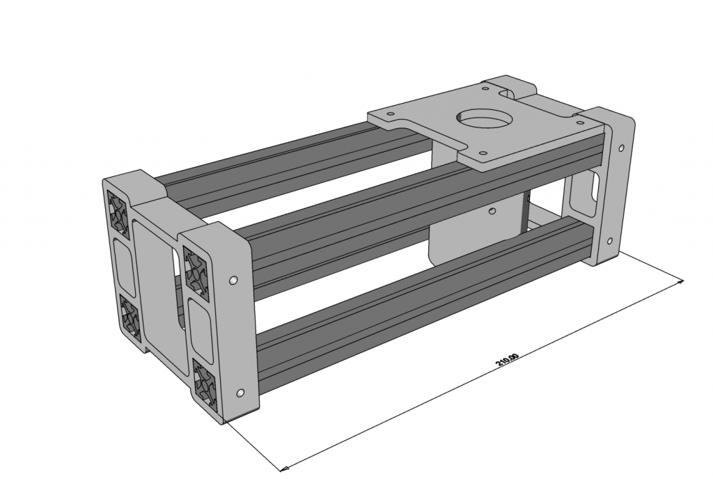
In this way, the plate has a strong and direct connection to the loudspeaker stand. This results in a compact yet sturdy solution.
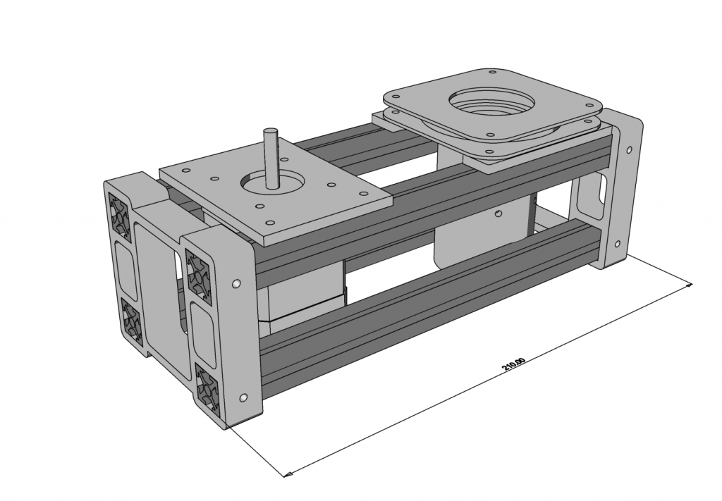
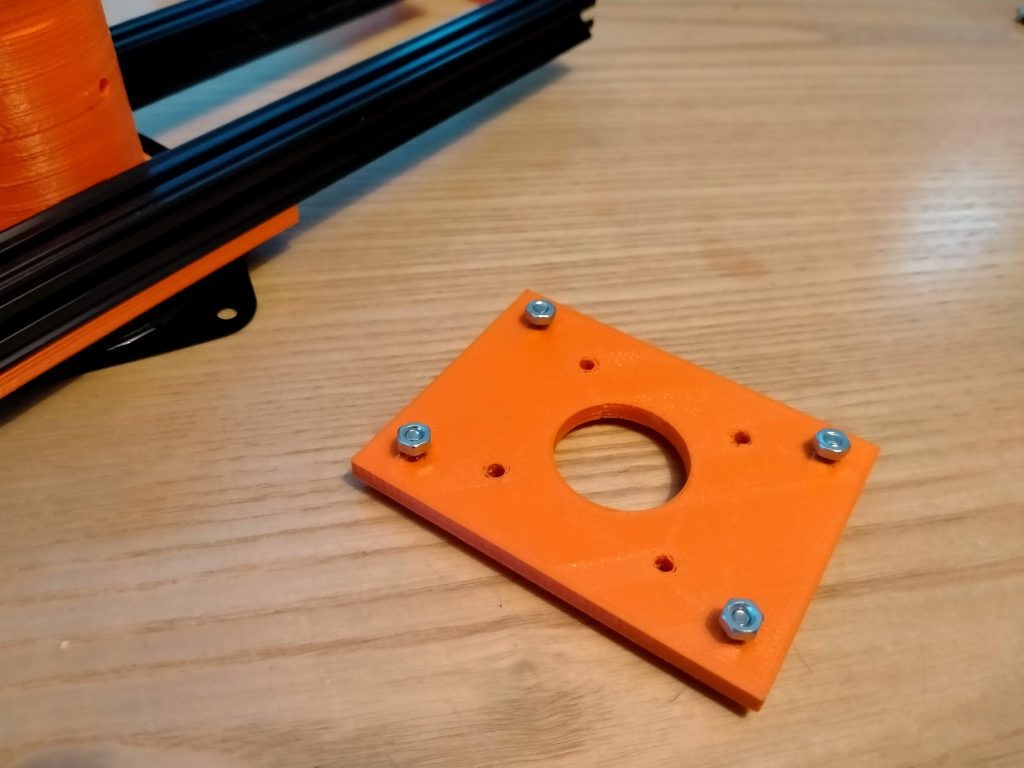
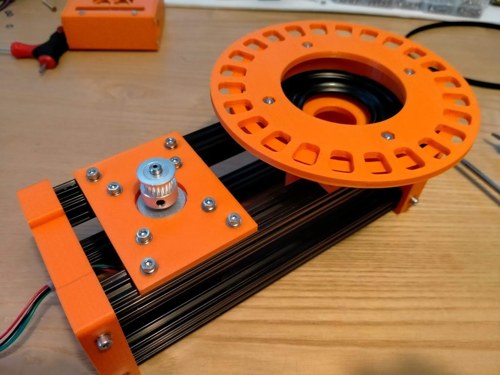
The motor is hosted on a 3D printed plate part and connects to the structure:
The driving mechanism is carried out using a GT2 toothed belt and a couple of pulleys on the motor shaft and the swivel plate. We suggest using a 5 mm 20 teeth pulley on the motor shaft and we designed a 3D printed 180 teeth pulley to be used on the plate.
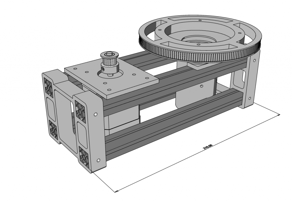
A GT2 closed loop timing belt with 450 mm length fits the design perfectly (not shown on renderings).
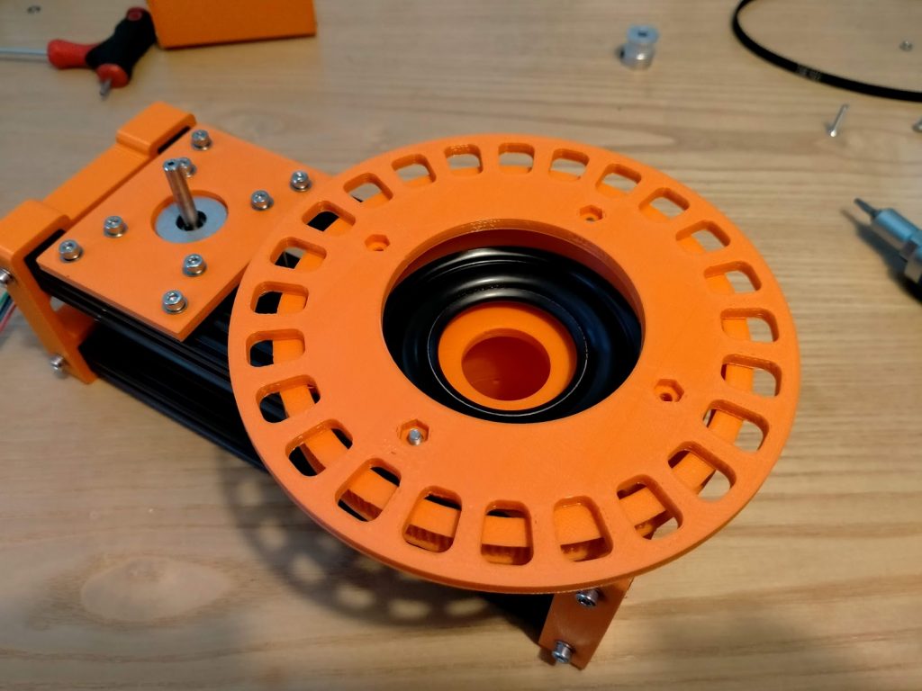
To complete the turntable we designed a lightweight plate that is bolted on top of the swivel plate pulley. This allows for easier placement of the loudspeaker to be measured.
As the other 3D printed parts, the top plate can be modified to suit the electro-acoustical device to be tested.
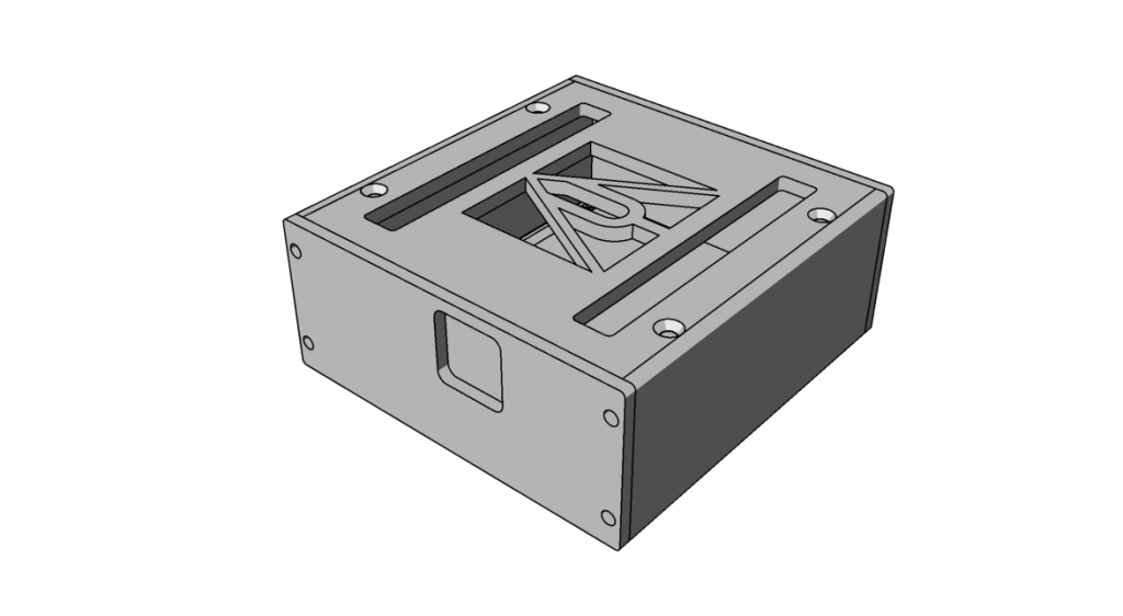
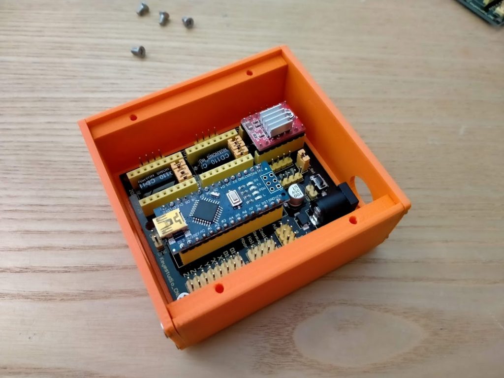
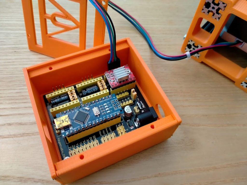
We also designed a simple 3D printed box to host the Arduino CNC shield v4 and Arduino Nano.
Sourcing Parts
This is a tentative list of potential part sources; however, please note that we are unable to update it regularly. If certain parts become unavailable through the provided links, we recommend conducting a web search to identify a suitable substitute source or part.
3D Printed plastic parts:
The .stl files of the parts to be printed are available at the following link:
For our prototypes, we printed parts in PLA with 20% filling and 0.2 mm resolution. We suggest printing with 100% filling for production parts.
Swivel plate:
This part can be found from several sources searching for “lazy susan 3 inches”, as an example:
https://www.amazon.com/Turntable-Bearings-Rotating-Bearing-Capacity/dp/B07PWW8T99/
NEMA-17 motor:
Any NEMA-17 motor with similar characteristics as the Wantai 42BYGHW811 we used can fit, an example of a possible source in the EU:
https://www.ebay.com/itm/152446186930
Bolts and nuts:
You will need at least, but expect to have plenty of spares:
20 x M3*8 socket head screws
24 x M3 nuts
4 x M3*16 flat head screws
16 x M3 washers
16 x M3*6 flat head screws (electronics box)
5 x M3*6 socket head screws (electronics box)
5 x M3 nuts (electronics box)
Motor pulley GT2 20 teeth 5 mm and GT2 Closed Timing Belt 450 mm:
These items should be easy to find, a possible source in the EU:
https://www.ebay.com/itm/151448217271
https://www.ebay.com/itm/153645018471
4 x 210mm OpenBeam aluminum beams:
https://www.makerbeam.com/openbeam-210mm-4p-black-openbeam.html
Arduino Nano and A4988 motor driver:
There are too many options here, research on your preferred supplier should return several results.
We used very cheap Arduino clones and A4988 drivers from a Chinese supplier.
Even the original Arduino Nano sells in packs:
https://store.arduino.cc/nano-every-pack
we suggest getting some spare boards.
CNC Shield v4 for Arduino Nano:
We get our board here:https://www.keyestudio.com/products/keyestudio-cnc-shield-v40-board-for-arduino-nano
This might be the only component that has a limited set of suppliers, unfortunately looks like the market is flooded with bad clones of this design. The ones with red printed circuit board seem to be bad functioning poorly copied clones as shown here:
https://www.instructables.com/Fix-Cloned-Arduino-NANO-CNC-Shield/
If you have difficulties finding the CNC Shield for Arduino Nano you have two possible solutions:
1. Create your own shield, instruction on how to connect an A4988 driver to the Arduino board are very easy to find on the Internet. You will need only to add a capacitor and provide the connections.
2. Use Arduino Uno with CNC Shield v3, in this case, you will have to redesign the electronics box.
12V Power Supply:
Any 12V 2A power supply can be used, we used one which comes with the CLIO system.
Building Instructions
Check that the swivel plate bearing is rotating without friction, if needed apply specific grease or oil. In our case, the ball bearing we get was very dry and needed a good amount of oil.
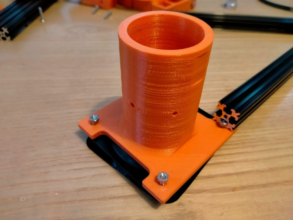
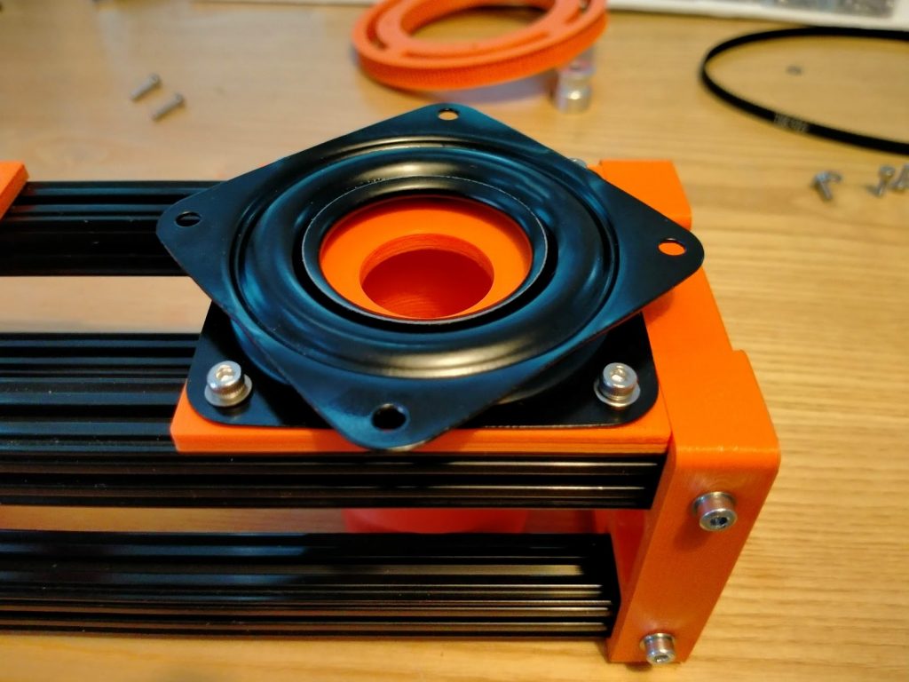
Start assembling the swivel plate to the 3D printed loudspeaker stand adapter. Bolt 4 x M3*8 socket head screws through the holes.
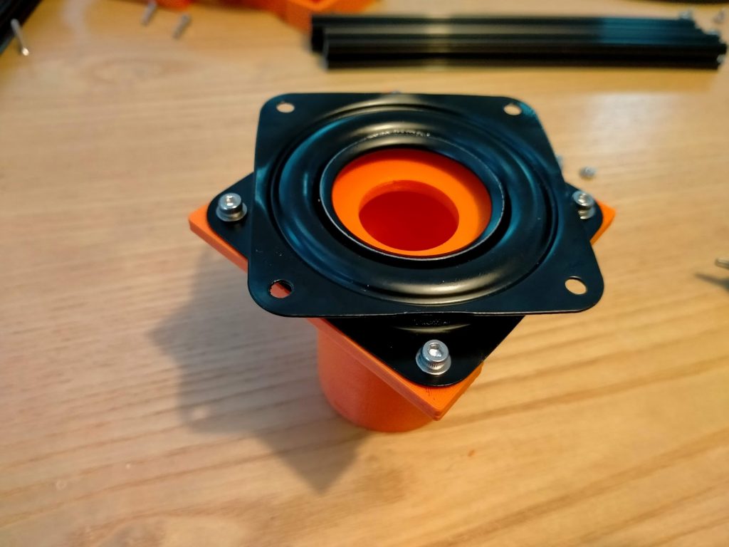
Add nuts without tightening them, as shown in the pictures:
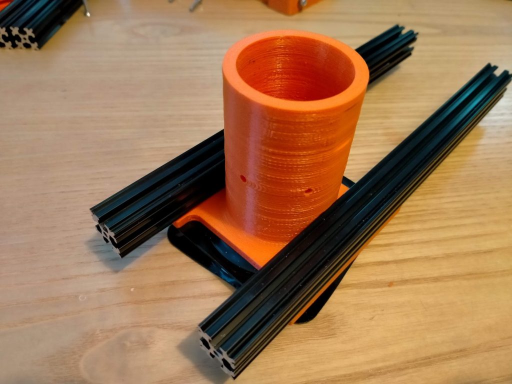
Gently slid the beam over the nuts, if needed loose the nuts:
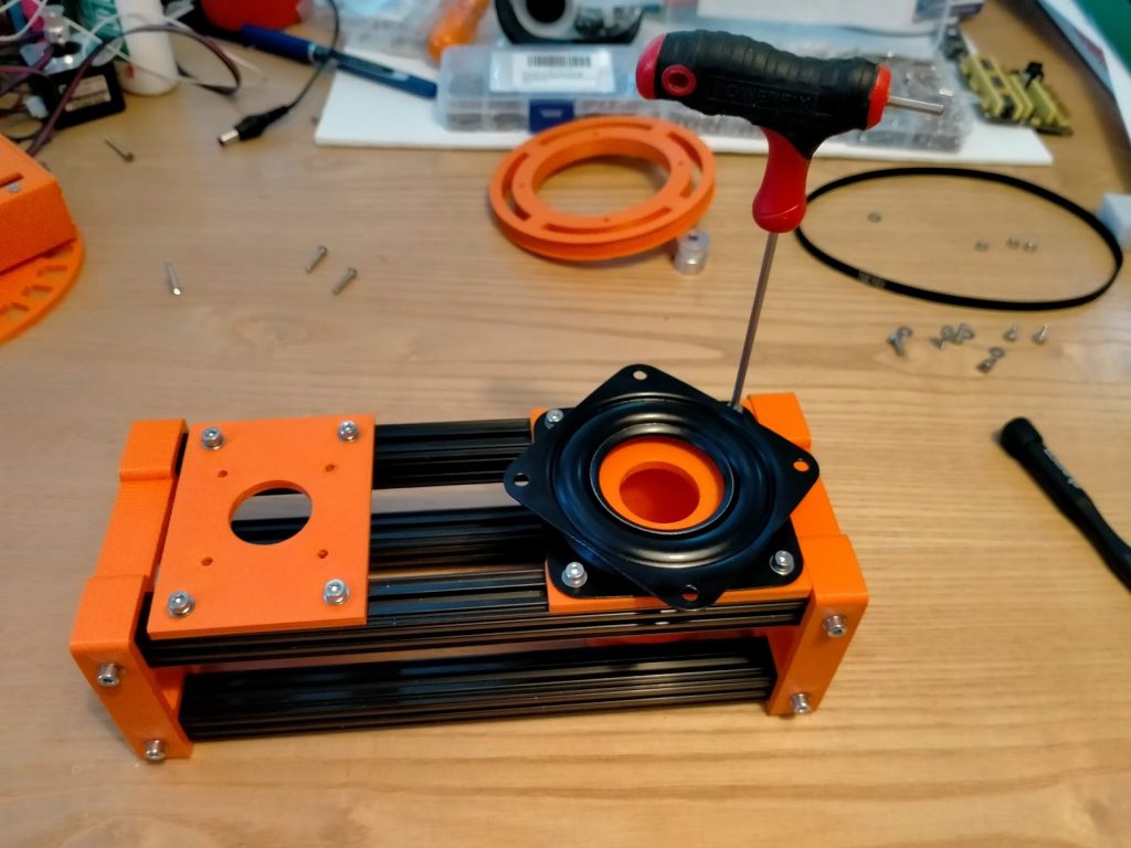
Prepare the NEMA-17 3D printed plate part in the same way using 4 x M3*8 screws:
And slid also this part into the beam rails:
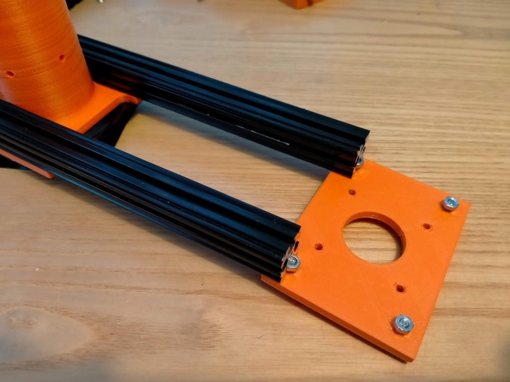
The assembly should look like this:
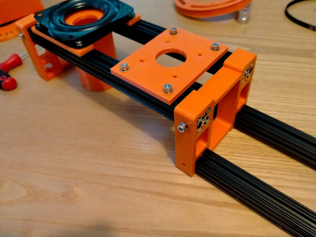
Now add the terminal blocks to the assembly by inserting the beam end into the terminal blocks. The terminal block part might be little narrow, use a reasonable amount of strength to fit.
Repeat for the other 3D printed terminal block:
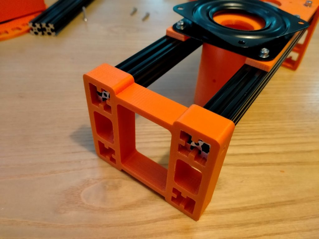
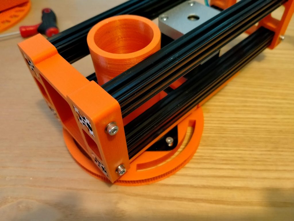
Secure the terminal blocks using nuts and 4 x M3*8 screws, you can insert the nut into the beam rail until the hole of the nut is coincident with the hole in the terminal block side, then gently tighten the screw.
Once all 4 screws are in place the assembly should look like:
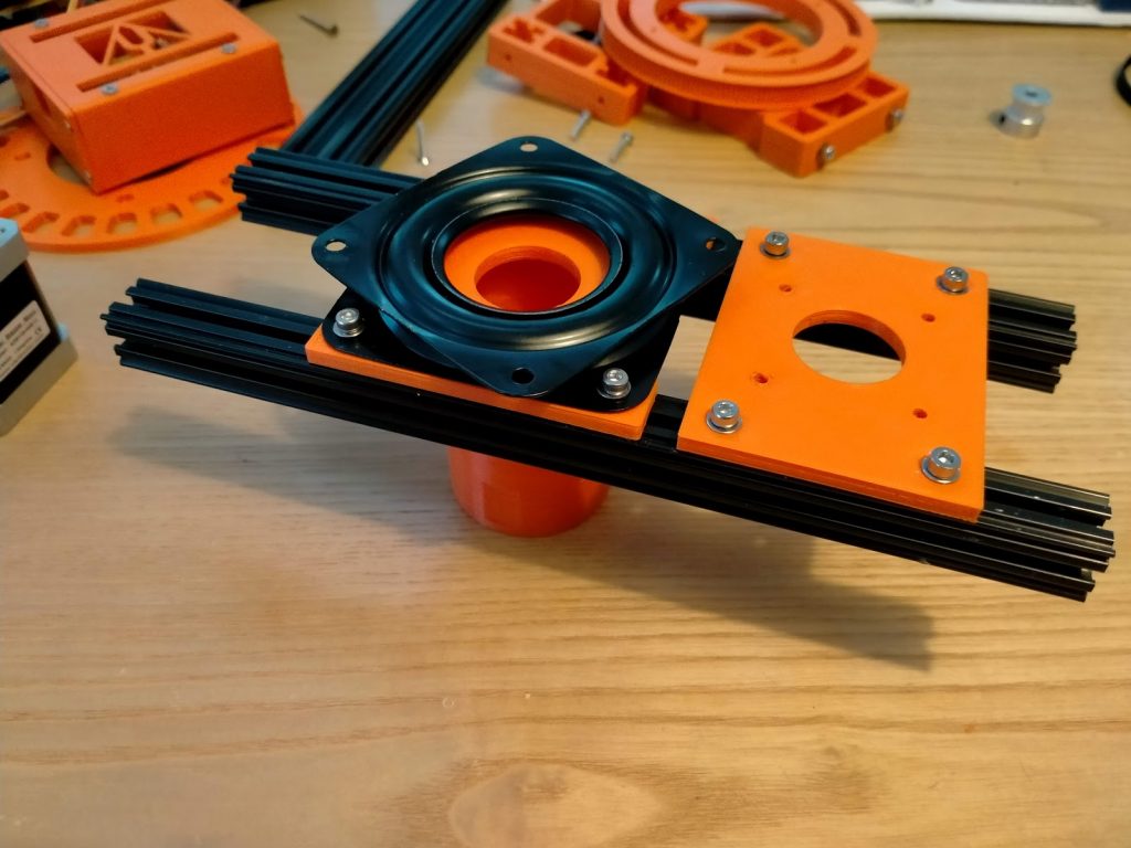
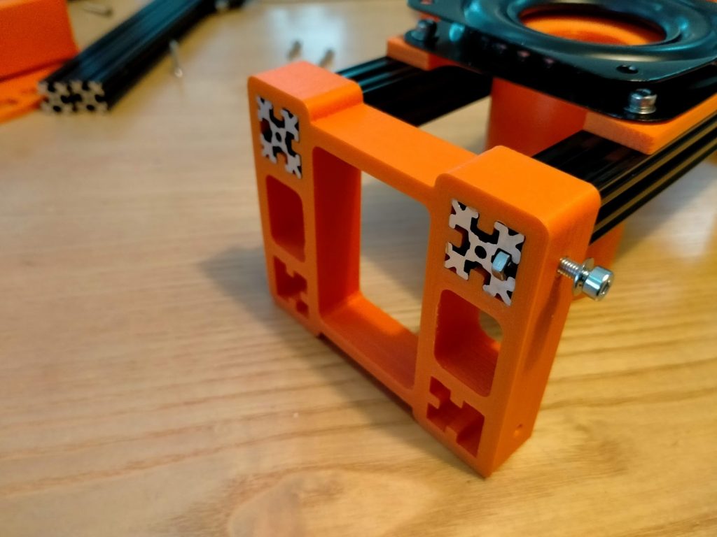
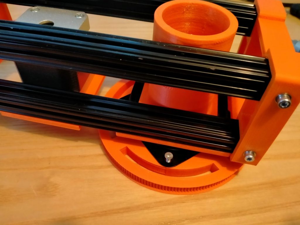
Now insert the two remaining aluminum beams, and secure in place using nuts and screws:
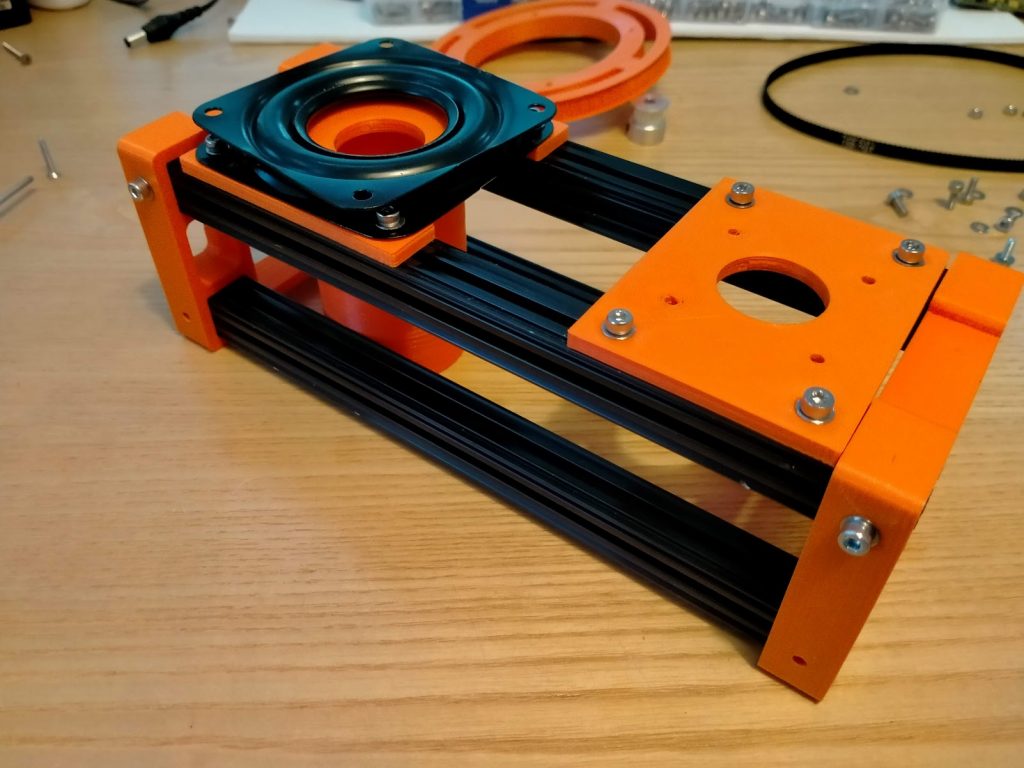
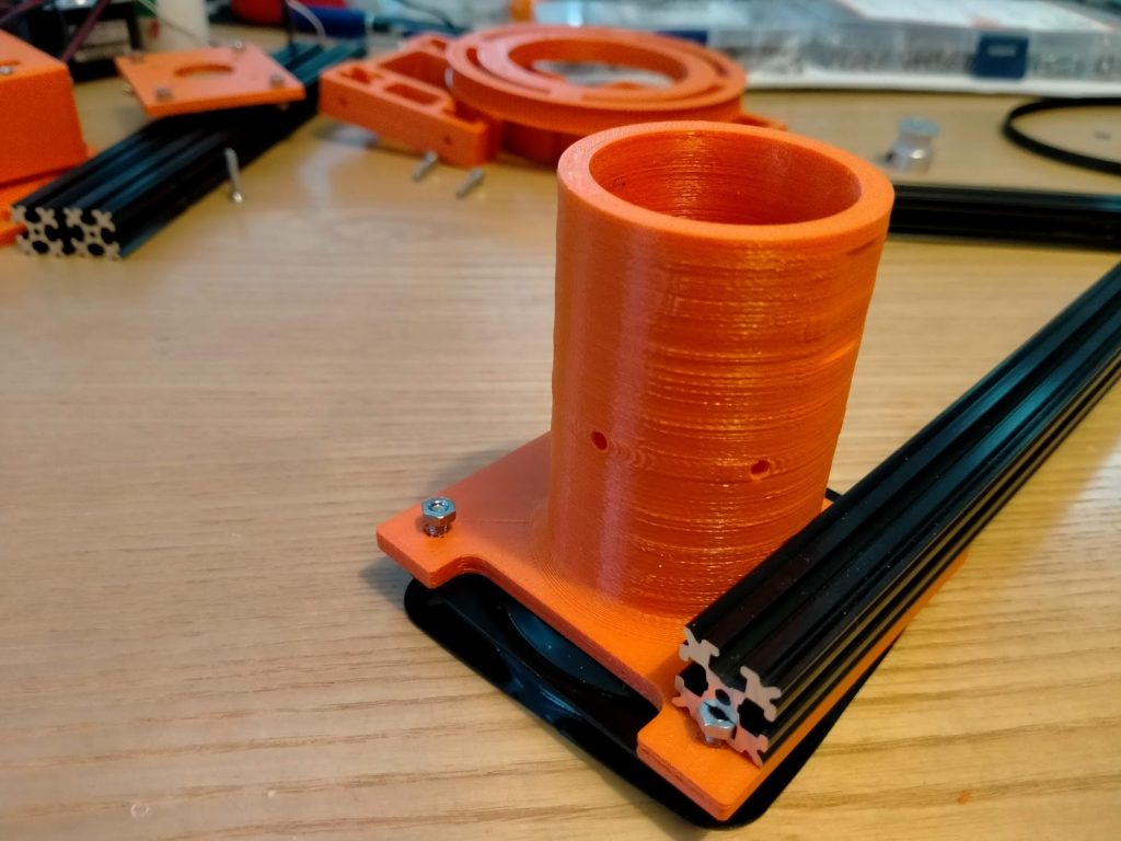
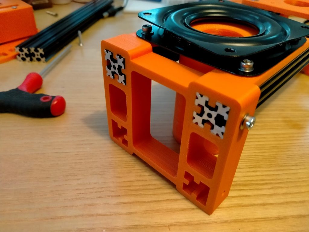
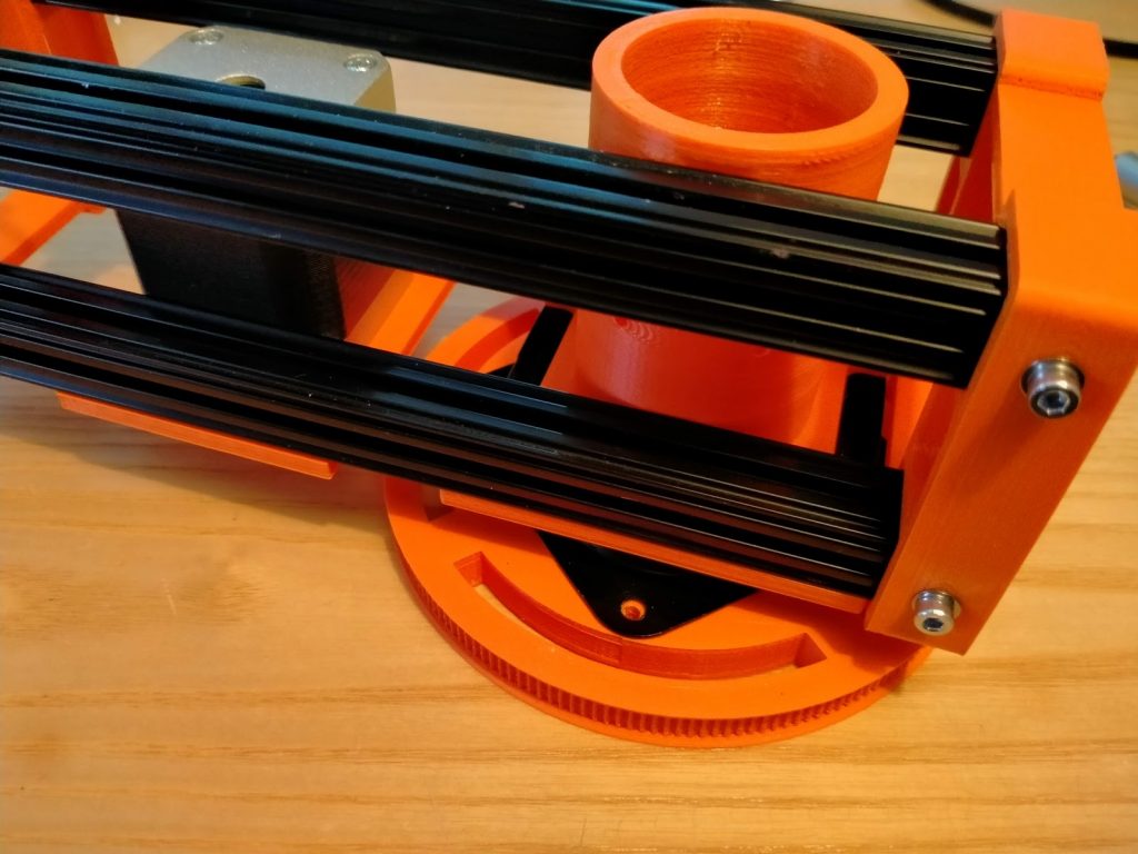
It is time to fix in position the swivel plate/stand adapter part. Slide the part all the way to the side until it reaches the terminal block:
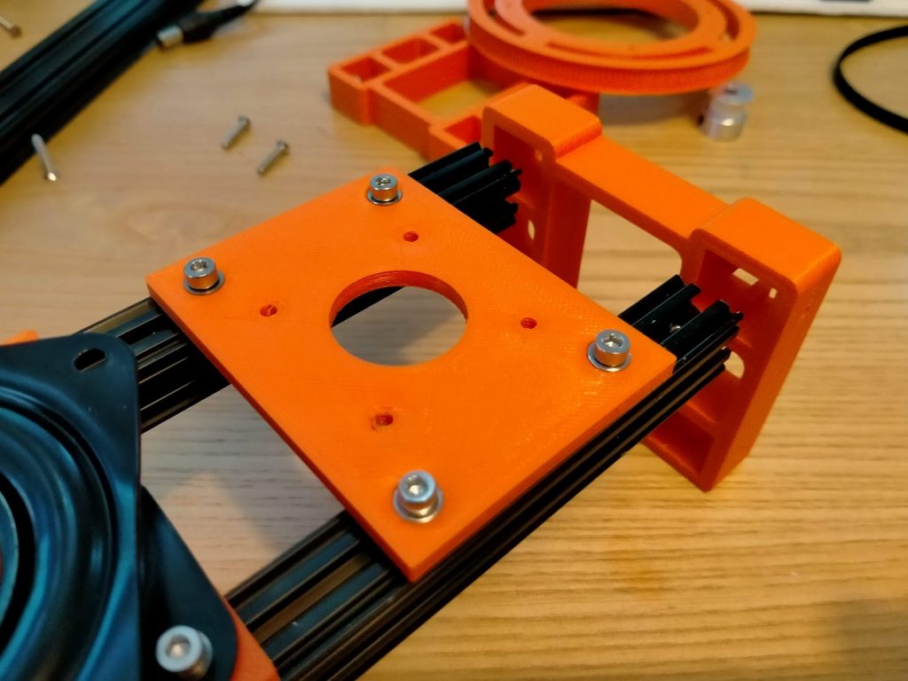
Gently tighten the screws until the part is firmly in place:
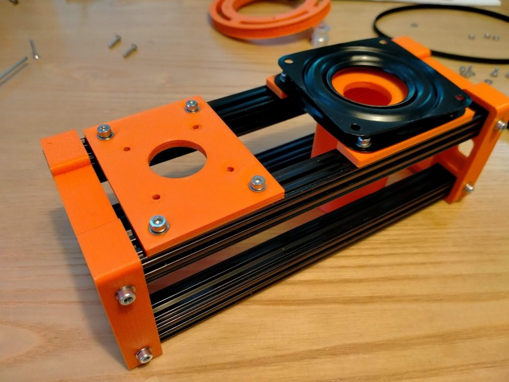
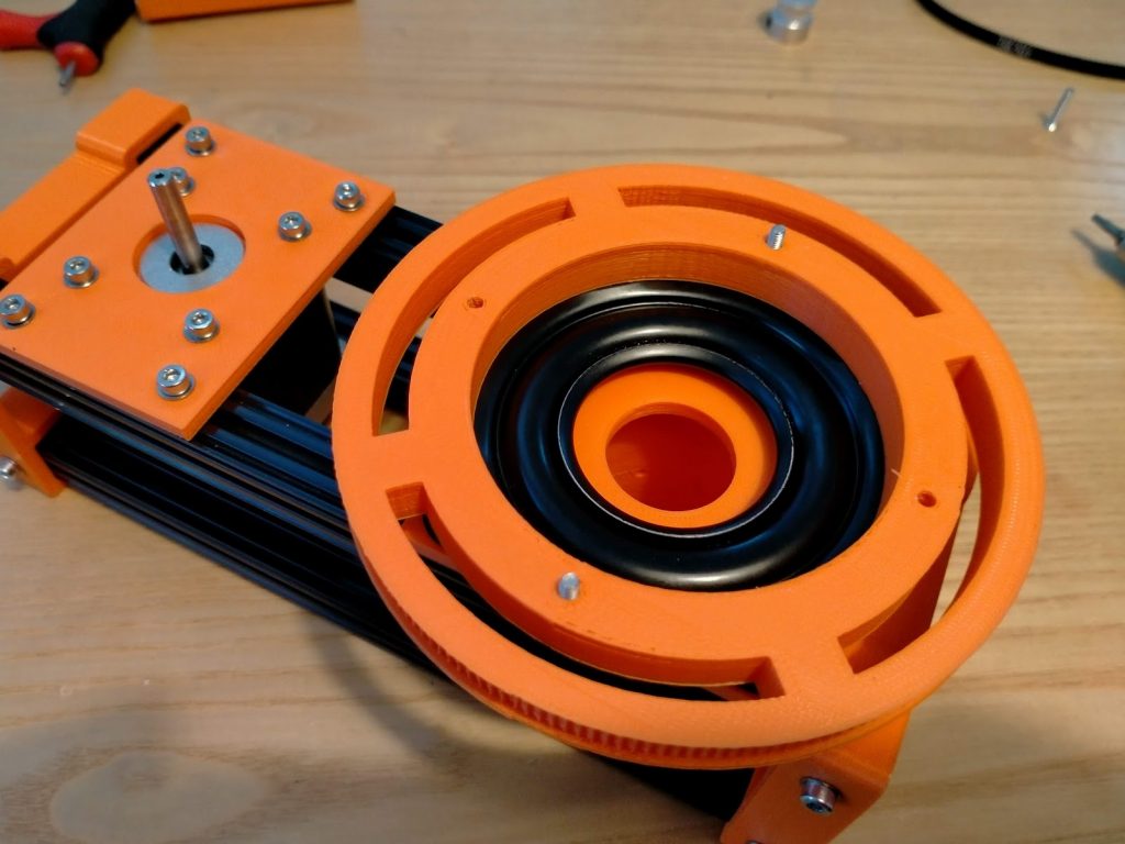
Attach the NEMA-17 motor to its plate using 4 x M3*8 screws (this step can also be done before, i.e. the motor can be mounted onto the plate before sliding the plate onto the beams, do as you please).
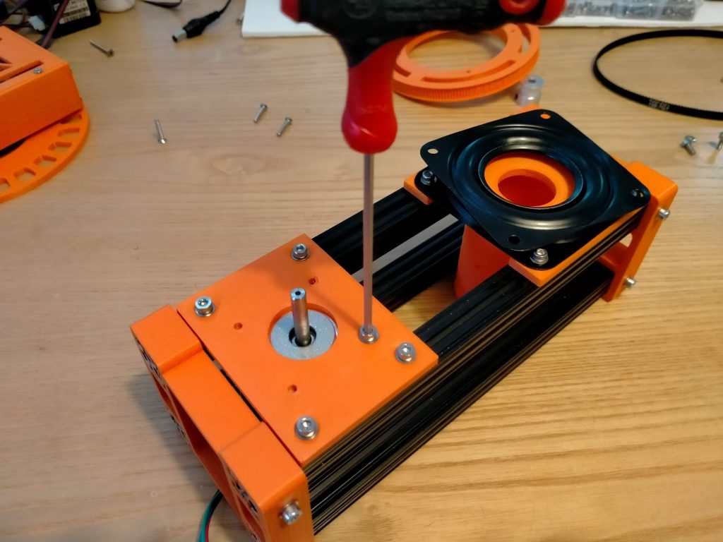
You should end up with the motor firmly connected to the plate and the plate free to slid onto the rails.
Now take the 3D printed pulley and put the assembly upside down on it. Align the swivel plate holes to the pulley holes.
Insert an M3*16 flat head screw.
Do the same to the hole in the other end:
You should get to this point:
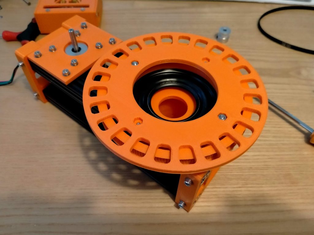
Now put in place the 3D printed top plate part, and secure the two screws using nuts.
Note: The .stl collection features also a spacer.stl part which is a 14 mm ring to be eventually placed between pulley and tabletop. In this case you will need 30 mm screws. This part move away the tabletop from the motor shaft and belt, in some cases it can be useful such when you have loudspeaker boxes with foots that can jam into the belt.
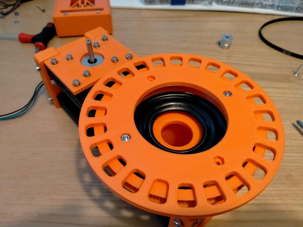
With the screws in place now the plate is free to rotate. Rotate it by 90 degrees and apply the other two screws (and nuts) to the assembly.
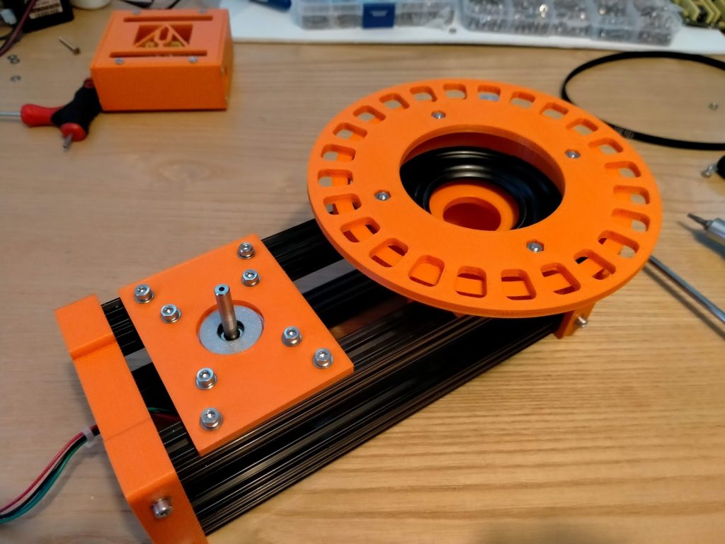
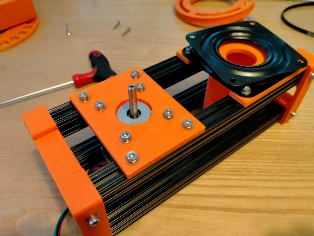
Mount the GT2 20 teeth pulley to the motor shaft, be careful to align the height of the two pulleys. This alignment is important to let the belt work properly.
Add the belt.
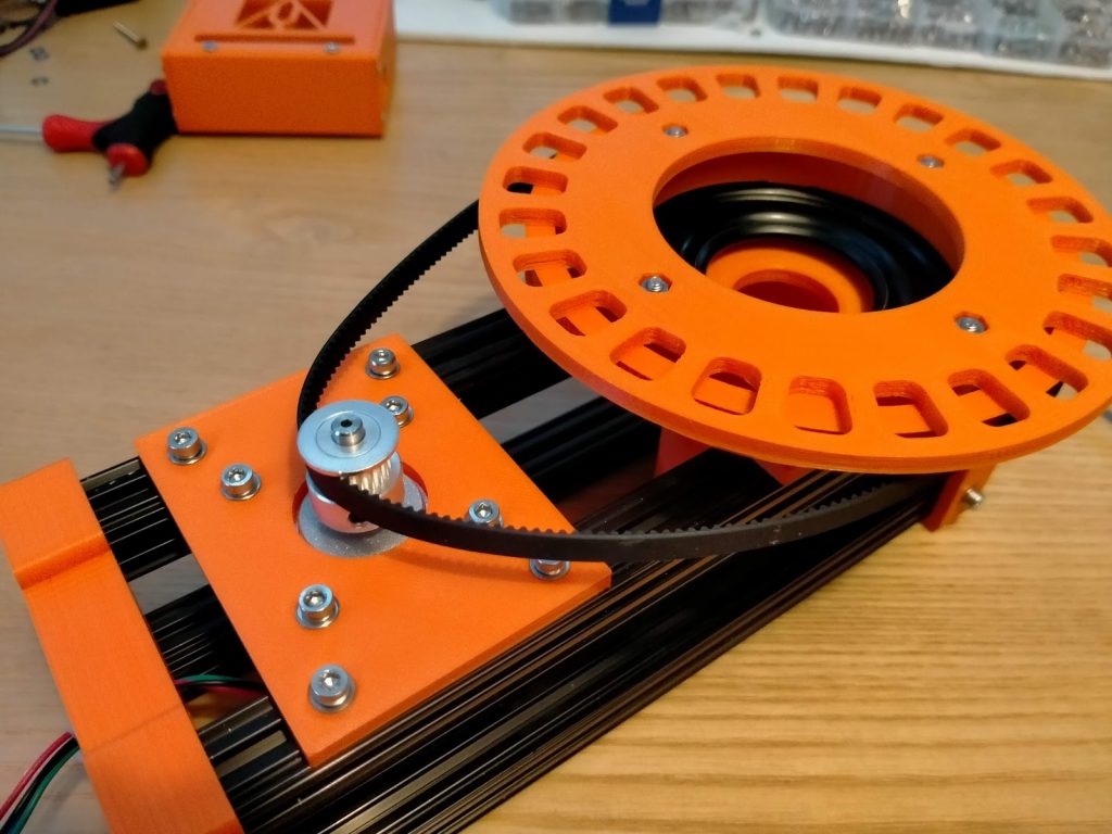
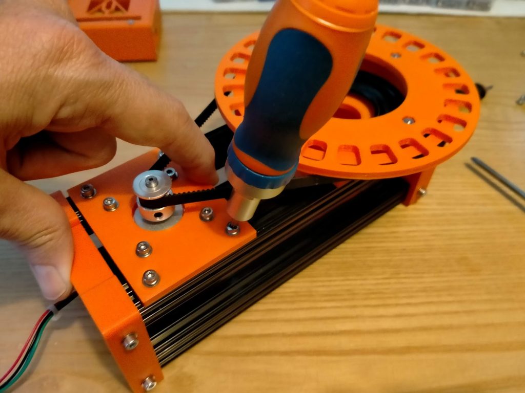
Tension the belt by sliding the motor plate to the left, do not overtight the belt. Once the tension is correct, tighten the motor plate screws to the beam structure. The belt tension can be optimized later during turntable testing.
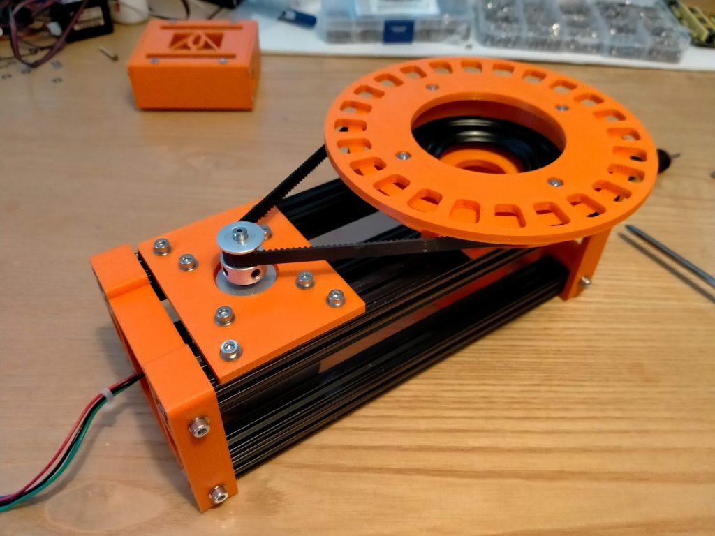
The turntable is complete and ready to spin!
Assembling and setting up the electronics:
First of all the Arduino should be loaded with Grbl firmware. At the time of writing the latest Grbl version is 1.1 and we carried out our tests using this version.
You need to have Arduino IDE installed and working on your PC:
https://www.arduino.cc/en/software
Instruction on how to get and compile Grbl are available at the official Wiki of the project:
https://github.com/gnea/grbl/wiki
Follow the instruction to compile and load Grbl to the Arduino (there are also Grbl .ino binary files available on the Internet which you can load to the board using a binary sketch uploader).
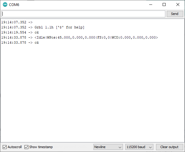
Once Grbl is loaded you can connect to the Arduino using the Serial Monitor Tool of the IDE and check if Grbl answers correctly:
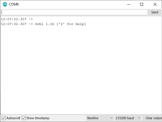
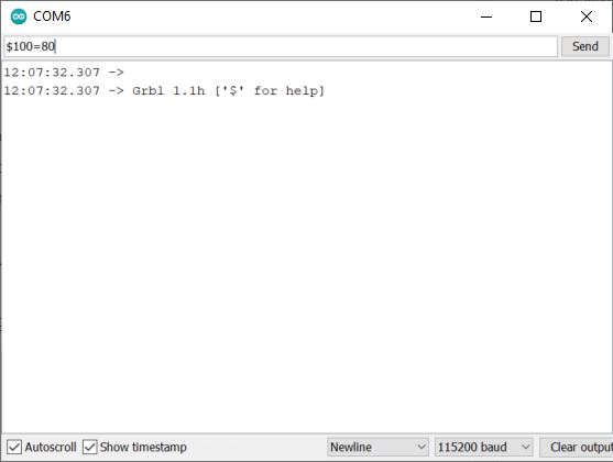
This allows also us to set up few Grbl variables to suit our needs. In fact, Grbl does not accept polar coordinates. We will use the x-axis not as a linear movement but as a polar rotation. Grbl is unaware of this and will just consider our commands as given in linear mm where in fact we are using rotation degrees. First of all, we need to instruct Grbl on the conversion factor $100 for the x-axis, this is in motor steps per mm, then in our case means step per degree.
Let’s do the math, our motor has 1.8 degrees resolution, that is 200 steps per 360 degrees revolution. We set up motor driver A4988 to use 16x microstepping (this enhances resolution but reduces motor torque), thus we have 16*200=3200 steps per 360 degrees revolution. We need also to consider our pulleys ratio which is 180/20=9. This gives us 28800 steps per 360 degrees, which is 80 steps per degree. We need then to instruct Grbl to use this factor:
Other settings we should set up in Grbl are $110=1440 maximum feed rate (speed) in degrees/minute (we empirically found out this value as a good compromise between maximum speed and needed torque, we didn’t do the math), we can also leave the acceleration rate $120 to the default 10 degrees/second^2. The last setting we might want to change from Grbl default is the $1 Step idle delay. By default Grbl disables the stepper motors after a movement, to avoid this we should set $1=255.
We need also to set $10=0, in this way Grbl status report returns WPos (Work Position) instead the default MPos (Machine Position). Using the above setting a ‘?’ status report query command will respond with a string:
<Idle|WPos:0.000,0.000,0.000|FS:0,0|WCO:0.000,0.000,0.000>
The remaining electronics assembly is straightforward, just put the Arduino Nano onto the CNC Shield V4 and an A4988 motor driver onto the x-axis plug.
We need to properly set up jumpers on CNC Shield V4 to use the 16x microstepping feature of the A4988 motor driver. The CNC Shield usually arrives with jumpers mounted for each motor driver, you should leave the jumpers on since when all three jumpers are in place the microstepping is set to 16x.
The electronics box assembly also does not need any instructions. Use the M3*6 flat head screws to connect the box parts.
The only remaining connection is the one between the motor and the CNC Shield board, connect the motor cable to the x-axis output of the board:
The motor connector has no polarity, thus there is a 50% chance to plug it correctly. By correctly we mean that a positive value of the x-axis in Grbl should match a clockwise rotation of the turntable.
DO NOT PLUG/UNPLUG THE MOTOR WHEN THE CNC BOARD IS POWERED AS THIS CAN DAMAGE THE ELECTRONICS.
Be careful as we actually blew out two Arduinos and one A4988 driver in this way during development. If you need to change the motor connector polarity, power off the CNC Board before.
Follow instructions here to set up the A4988 current limit.
Testing the turntable
Now we can try to move the first steps with our turntable. With the electronics powered up and connected to the PC, we can open the Serial Monitor tool of the Arduino IDE and send the first moving command to the turntable.
We can start with a simple 15 degrees turn by typing the command:
G1X45F360
The turntable should rotate clockwise by 45 degrees. At the end of the movement, Grbl should report using the ‘?’ command its status and position.
If the movement is not smooth or there is no movement at all you should check:
- The connection between the motor and CNC Shield
- Proper A4988 current setting
- Proper alignment between pulleys
- Belt tension, this should be not too tight neither too loose
Notice that there is a little hysteresis at the end of the rotation due to the swivel plate tolerance and belt tension, this is clearly visible when the table is unloaded but disappears when under load. We think this is related to the swivel plate’s simple mechanical structure. The unloaded top plate, which is connected to the pulley, tends to flex when the belt tensions it. When loaded the weight tends to counteract the belt tension force.
We can send back the turntable to the starting position using a G1X0F360 command and try a complete revolution with higher speed by sending a G1X360F720 command followed by a G1X0F720 command. Check again for the smoothness of movement and eventually adjust belt tension and motor shaft pulley position if needed. Check also that the swivel plate bearing is free to move.
If everything is OK we can try to push our turntable to its maximum speed with a double twist by G1X720F1440 followed by G1X0F1440.
Feel free to experiment using loads on the turntable. We run a test using some heavy “classical” textbooks as a weight.
Using the turntable with CLIO
The turntable is fully supported by our CLIO 12.62 and CLIO Pocket 2.20 software releases.
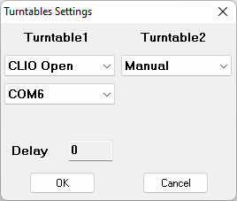
With CLIO 12 you can simply connect the turntable selecting CLIO Open from the dropdown box in Turntable Settings dialog:
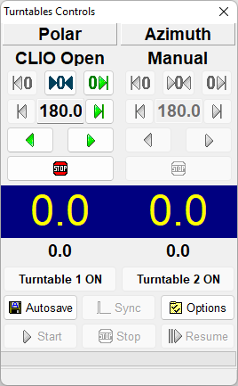
The turntable can be then connected and controlled through the Turntables Controls panel:
Similarly in CLIO Pocket Options a Medusa/Autosave tab has been added. The turntable can be connected and controlled from this dialog:
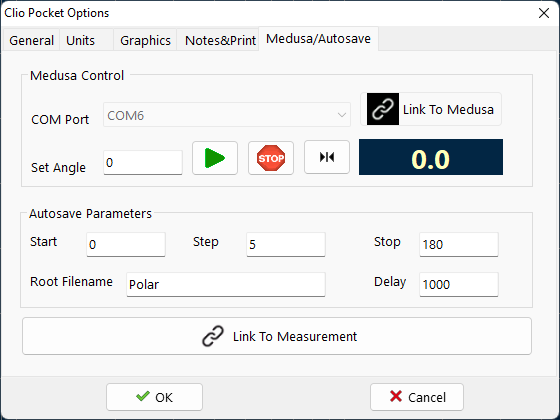
The above methods should be used to connect and control the turntable using CLIO and CLIO Pocket.
Turntable control and auto-save procedure using CLIO QC scripting
This control method and auto-save procedure are outdated since now CLIO software can directly control the turntable, nevertheless we will leave the following examples here as a future reference and to show a different approach.
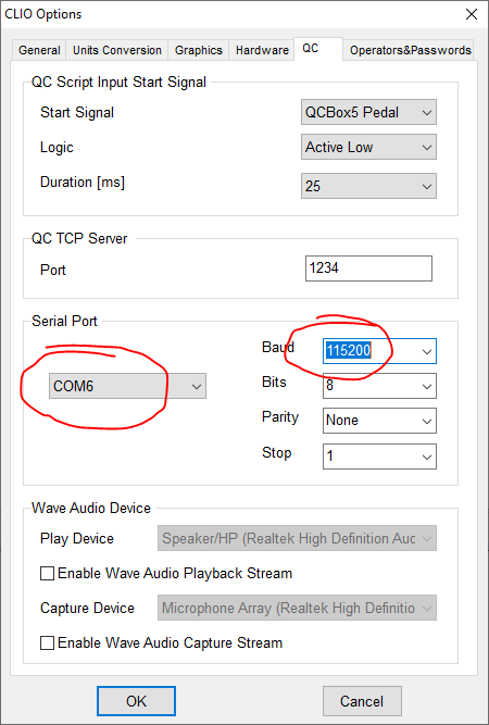
Serial Port should be correctly set up in CLIO Options:
This is an example QC script to carry out a polar 0 to 180 scan line with 15 degrees resolution:
[GLOBALS]
SERIALMONITOR=1
OPENSERIAL=1
SERIALOUTCR=1
[PERFORM]
DELAY=2000
[MLS]
OUT=-32.0 dBV
INA=-30
INB=-30
REFERENCE=REFERENCE.MLS
LIMITS=NONE
SAVEBINARY=1
SAVEONGOOD=1
SAVENAME=TEST 0
[PERFORM]
SERIALOUT=G1X15F1440@H0D
[PERFORM]
DELAY=2500
COMMENT=15
[MLS]
OUT=-32.0 dBV
INA=-30
INB=-30
REFERENCE=REFERENCE.MLS
LIMITS=NONE
SAVEBINARY=1
SAVEONGOOD=1
SAVENAME=TEST 1500
[PERFORM]
SERIALOUT=G1X30F1440@H0D
[PERFORM]
DELAY=2500
COMMENT=30
[MLS]
OUT=-32.0 dBV
INA=-30
INB=-30
REFERENCE=REFERENCE.MLS
LIMITS=NONE
SAVEBINARY=1
SAVEONGOOD=1
SAVENAME=TEST 3000
[PERFORM]
SERIALOUT=G1X45F1440@H0D
[PERFORM]
DELAY=2500
COMMENT=45
[MLS]
OUT=-32.0 dBV
INA=-30
INB=-30
REFERENCE=REFERENCE.MLS
LIMITS=NONE
SAVEBINARY=1
SAVEONGOOD=1
SAVENAME=TEST 4500
[PERFORM]
SERIALOUT=G1X60F1440@H0D
[PERFORM]
DELAY=2500
COMMENT=60
[MLS]
OUT=-32.0 dBV
INA=-30
INB=-30
REFERENCE=REFERENCE.MLS
LIMITS=NONE
SAVEBINARY=1
SAVEONGOOD=1
SAVENAME=TEST 6000
[PERFORM]
SERIALOUT=G1X75F1440@H0D
[PERFORM]
DELAY=2500
COMMENT=75
[MLS]
OUT=-32.0 dBV
INA=-30
INB=-30
REFERENCE=REFERENCE.MLS
LIMITS=NONE
SAVEBINARY=1
SAVEONGOOD=1
SAVENAME=TEST 7500
[PERFORM]
SERIALOUT=G1X90F1440@H0D
[PERFORM]
DELAY=2500
COMMENT=30
[MLS]
OUT=-32.0 dBV
INA=-30
INB=-30
REFERENCE=REFERENCE.MLS
LIMITS=NONE
SAVEBINARY=1
SAVEONGOOD=1
SAVENAME=TEST 9000
[PERFORM]
SERIALOUT=G1X105F1440@H0D
[PERFORM]
DELAY=2500
COMMENT=105
[MLS]
OUT=-32.0 dBV
INA=-30
INB=-30
REFERENCE=REFERENCE.MLS
LIMITS=NONE
SAVEBINARY=1
SAVEONGOOD=1
SAVENAME=TEST 10500
[PERFORM]
SERIALOUT=G1X120F1440@H0D
[PERFORM]
DELAY=2500
COMMENT=120
[MLS]
OUT=-32.0 dBV
INA=-30
INB=-30
REFERENCE=REFERENCE.MLS
LIMITS=NONE
SAVEBINARY=1
SAVEONGOOD=1
SAVENAME=TEST 12000
[PERFORM]
SERIALOUT=G1X120F1440@H0D
[PERFORM]
DELAY=2500
COMMENT=120
[MLS]
OUT=-32.0 dBV
INA=-30
INB=-30
REFERENCE=REFERENCE.MLS
LIMITS=NONE
SAVEBINARY=1
SAVEONGOOD=1
SAVENAME=TEST 12000
[PERFORM]
SERIALOUT=G1X135F1440@H0D
[PERFORM]
DELAY=2500
COMMENT=135
[MLS]
OUT=-32.0 dBV
INA=-30
INB=-30
REFERENCE=REFERENCE.MLS
LIMITS=NONE
SAVEBINARY=1
SAVEONGOOD=1
SAVENAME=TEST 13500
[PERFORM]
SERIALOUT=G1X150F1440@H0D
[PERFORM]
DELAY=2500
COMMENT=150
[MLS]
OUT=-32.0 dBV
INA=-30
INB=-30
REFERENCE=REFERENCE.MLS
LIMITS=NONE
SAVEBINARY=1
SAVEONGOOD=1
SAVENAME=TEST 15000
[PERFORM]
SERIALOUT=G1X165F1440@H0D
[PERFORM]
DELAY=2500
COMMENT=165
[MLS]
OUT=-32.0 dBV
INA=-30
INB=-30
REFERENCE=REFERENCE.MLS
LIMITS=NONE
SAVEBINARY=1
SAVEONGOOD=1
SAVENAME=TEST 16500
[PERFORM]
SERIALOUT=G1X180F1440@H0D
[PERFORM]
DELAY=2500
COMMENT=180
[MLS]
OUT=-32.0 dBV
INA=-30
INB=-30
REFERENCE=REFERENCE.MLS
LIMITS=NONE
SAVEBINARY=1
SAVEONGOOD=1
SAVENAME=TEST 18000
[PERFORM]
SERIALOUT=G1X0F1440@H0D
[PERFORM]
DELAY=10000
COMMENT=RETURN TO ZERO
[PERFORM]
CLOSESERIAL=1
[STOP]
Before running the script the REFERENCE.MLS on-axis LogChirp measurement must be carried out and saved with all the proper settings.
Turntable control and CLIO QC TCP/IP auto-save procedure using Scilab
The remote control of CLIO QC TCP/IP from Scilab is already covered in our Application Note Develop Custom Tests With CLIO QC TCP/IP Remote Control Through SCILAB.
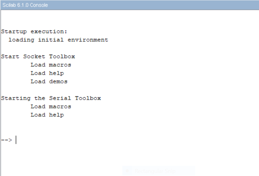
Following example has been implemented in Scilab 6.1 on Windows 10. The following toolboxes shall be active in Scilab:
- Serial Toolbox https://github.com/sengupta/Scilab-Serial
- Socket Toolbox http://www.reveyrand.fr/SOCKET2.html
The following Scilab code connects to the turntable and CLIO QC TCP/IP, and then runs a set of 73 measurements from -180 to 180 with 5 degrees step saving each measurement with the CLIO polar naming scheme:
TEST <degrees*100>.mls
// Scilab script to control Audiomatica Open Source Turntable
// and CLIO QC TCP/IP and collect a simple polar scan line
//
// 26-08-2021 dp@audiomatica.com

clear
funcprot(0);

// define functions
function [rd]=TCPsend(socket,sendstr)
    SOCKET_write(socket,sendstr)
    sleep(10)
    rd=SOCKET_read(socket)
    while isempty(rd)
        sleep(10)
        rd=SOCKET_read(socket)
    end
endfunction

function rd=GOTOangle(h,angle)
    writeserial(h,"G1X"+string(angle)+"F1440"+ascii(13))
    sleep(100)
    rd=readserial(h)
    // wait until becomes 'Idle' again
    while isempty(strindex(rd,'Idle'))
        writeserial(h,'?')
        sleep(100)
        rd=readserial(h)
    end
endfunction

// Connect to Open Source Turntable
disp('Connecting to Open Source Turntable ...');
h=openserial(6,"115200,n,8,1");  //6 stands for COM6 (see toolbox docs)
sleep(100)
rd=readserial(h);
while isempty(strindex(rd,'Grbl'))
    sleep(100)
    rd=readserial(h)
end
disp('Connected to Open Source Turntable')

// Connect to CLIO QC TCP/IP server
disp('Connecting to CLIO QC TCP/IP server ...')
SOCKET_open(1,"localhost",1234)
rd=SOCKET_read(1)
disp(rd);

// set TCP/IP QC Working directory
disp('Setting QC Working directory ...')
TCPsend(1,"\[PERFORM]\")
TCPsend(1,'\QCWORKDIR=C:\\TEST_TURN\')
TCPsend(1,'\[]\')

// Measurement QC command
CRLF=char(13)+char(10);
QCstring="\[MLS]\"+CRLF+"\OUT=-24 dBu\"+CRLF;
QCstring=QCstring+"\IN=-40\"+CRLF;
QCstring=QCstring+"\REFERENCE=reference.mls\"+CRLF;
QCstring=QCstring+"\LIMITS=none\"+CRLF;
QCstring=QCstring+"\SAVEONGOOD=1\";

// range from -180 to 180 at 5 degrees step
for i=0:72
    angle=i*5-180;
    disp("Measuring "+string(angle)+" degrees")
    GOTOangle(h,angle)
    TCPsend(1,QCstring)
    TCPsend(1,"\[]\")
    filename='C:\TEST_TURN\test '+string(angle*100)+'.mls';
    disp("Saving "+filename)
    copyfile('C:\TEST_TURN\tcpresult.mls',filename)
end

// go back to zero
disp("Moving back to zero position ...")
GOTOangle(h,0)

// close connections
closeserial(h);
SOCKET_close(1);
Before running the Scilab script several things should be properly set and checked
A working directory where to put the script and the measurement files should be created, please avoid complex paths. The script needs to be edited with the specific path. In the example the path is C:\TEST_TURN, which turns in the following commands.
Instruct CLIO TCP/IP to use the path using:
- TCPsend(1,’\QCWORKDIR=C:\\TEST_TURN\’)
Instruct Scilab to copy the temporary file tcpresult.mls to the file with polar naming scheme:
- filename=’C:\TEST_TURN\test ‘+string(angle*100)+’.mls’;
- copyfile(‘C:\TEST_TURN\tcpresult.mls’,filename)
The on-axis reference.mls measurement with the correct settings (such as time windowing) should be present in the path.
CLIO QC with TCP/IP option should be running before executing the Scilab script.
The Scilab script should also be edited to set the correct COM port to which the turntable is connected, in our case was COM6:
- h=openserial(6,”115200,n,8,1″); //6 stands for COM6 (see toolbox docs)
As seen in the code comment the openserial command of the Serial Toolbox accepts an integer as a first parameter, this number is relative to the COM port: 1 – COM1; 2 – COM2 and so on.
Obviously the turntable must be connected to the COM port and ready to accept a serial connection.
Please notice that in order to tidy the Scilab code and also speedup TCP/IP communication we implemented two functions.
The first one is TCPsend, and is used to send commands to CLIO TCP/IP. In the previous Scilab scripts reported in the application note cited earlier we used to send commands with SOCKET_query() function. This function which is implemented in the Socket Toolbox has very poor performance, and introduces significant delays. Since the communication protocol with CLIO TCP/IP server is very simple, we replaced the SOCKET_query() with a SOCKET_write() followed by a polling of the read buffer using SOCKET_read() until there is a response.
function [rd]=TCPsend(socket,sendstr)
    SOCKET_write(socket,sendstr)
    sleep(10)
    rd=SOCKET_read(socket)
    while isempty(rd)
        sleep(10)
        rd=SOCKET_read(socket)
    end
endfunction
In our tests this proved to be very fast and running without issues.
The second function is GOTOangle(). This function sends the G1 movement command to the turntable using writeserial() and then polls the turntable Grbl status about each 0.1 s until the table is ‘Idle’, i.e. is not moving anymore. This function then release the control only when the table movement is complete.
function rd=GOTOangle(h,angle)
    writeserial(h,"G1X"+string(angle)+"F1440"+ascii(13))
    sleep(100)
    rd=readserial(h)
    // wait until becomes 'Idle' again
    while isempty(strindex(rd,'Idle'))
        writeserial(h,'?')
        sleep(100)
        rd=readserial(h)
    end
endfunction
Conclusions
The build we presented here it is an attempt to lay the grounds for an open-source approach to polar measurement testing hardware. The hardware we chose has some tolerances in the swivel plate which can cause a little hysteresis due to the belt tension. These effects are mitigated when the bearing is loaded and are much more visible when unloaded. Nevertheless, we were able to show that with minimal effort it is possible to build usable hardware. There also are many advantages in using a self-designed structure such as customizing it to suit specific measurement needs.
The Open Source approach, which uses standard components and protocols, means that there are no limits in improving the hardware, for example using a more precise bearing or a different drive mechanism. We expect customers to work on this and improve our basic design.
CLIO 12.62 and CLIO Pocket 2.2 software both supports the Audiomatica Open Source Turntable. In fact, in this way, we support control for any device using Grbl (plus our practice to consider degrees instead of millimeters in Grbl settings).
The Audiomatica Open Source Turntable is fully supported by Audiomatica CLIO and CLIO Pocket systems.
The turntable can be also controlled using Serial Communication via CLIO QC scripting, or it is possible to create software (Or a MATLAB, Scilab or Phyton script) that can control both the turntable and CLIO QC using TCP/IP protocol. Examples of both approaches are provided.